Stress-Free New Build: Your Webinar for a Smooth and Successful New Build Journey to an Energy Efficient and Sustainable Home.
Avoid Costly Mistakes: Master Your New Construction or Buying Journey
After this webinar you will have knowledge about

To hold discussions with the inspector or builder at eye level
After the webinar, you will most likely have more knowledge than some inspectors or construction companies. Discuss with the inspector and understand his report. Ask and negotiate with the contractor and ask for what you want.

Material science that determines quality
The choice of building materials, construction methods, building services, etc. determines the durability of your home and also its value development.

Future-orientated construction
Choose to ensure that your home is well prepared for climate change and is built in an energy-efficient and sustainable way, minimising running costs.
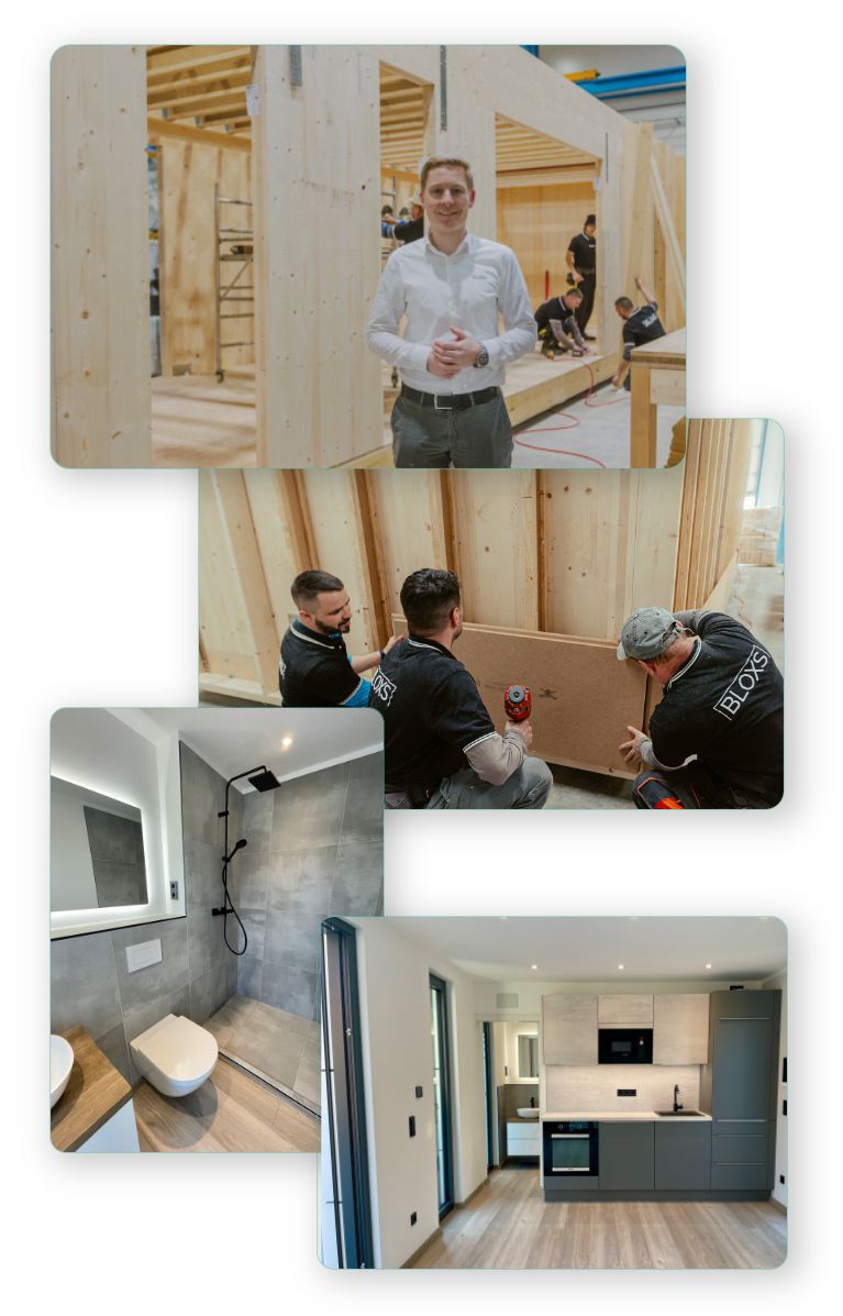
German engineering expertise of a real house manufacturer
Thomas, the speaker in the webinar, is the CEO of the German premium house construction company BLOXS and knows what he is talking about. Try to apply the expertise you have learnt to your new construction project in your home country.
‘DAS PREMIUM HAUS’ webinar
Get knowledge from Germany in house planning to avoid mistakes when building or buying a house
As the CEO of the German house construction company BLOXS GmbH, I’m thrilled to receive positive feedback about our high-quality construction methods worldwide. However, due to complexity, we can’t send our houses everywhere.
Many people are unaware of how material choices impact a house’s indoor climate, durability, and value. Making the right decisions is crucial, as mistakes can be costly. That’s why we’re offering the webinar “Das Premium Haus” with a total of over 7.5 hours of video. It provides specialist knowledge on important decisions in high quality-house planning and building based on German engineering, including recommendations for German brand products. We’ve acquired this knowledge through years of collaboration with German experts.
The webinar is designed to be easy for everyone to understand. Enjoy the webinar and gain valuable specialist knowledge for life!

‘DAS PREMIUM HAUS’ webinar
Get knowledge from Germany in house planning to avoid mistakes when building or buying a house
As the CEO of the German house construction company BLOXS GmbH, I’m thrilled to receive positive feedback about our high-quality construction methods worldwide. However, due to complexity, we can’t send our houses everywhere.
Many people are unaware of how material choices impact a house’s indoor climate, durability, and value. Making the right decisions is crucial, as mistakes can be costly. That’s why we’re offering the webinar “Das Premium Haus” with a total of over 7.5 hours of video. It provides specialist knowledge on important decisions in high-quality house planning and building based on German engineering, including recommendations for German brand products. We’ve acquired this knowledge through years of collaboration with German experts.
The webinar is designed to be easy for everyone to understand. Enjoy the webinar and gain valuable specialist knowledge for life!
Temporary Promotion
Get a 10% off coupon
Just leave your name and e-mail address and we will send you a 10% off coupon via email. Don’t hesitate too long, the promotion is limited in time:
Day(s)
hrs
min
sec
First Impressions of the Webinar
Valuable content, clearly explained

Get smart before building or buying a house
Empower yourself: choose your webinar

Full Course
460 min content
————–
> paid access <
> ask questions to Thomas <
The full package. Learn a wealth of specialist knowledge for life that will give you a big advantage when planning your home.

Discovery Course
40 min content
————–
> free access <
.
The exciting introduction. Get to know the system and its structure and gain your first valuable insights from the Full Course.